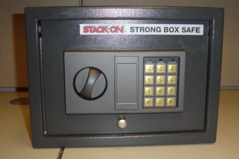
Stack On Strong Box Safe Manual
- Posted in:Admin
- 03/07/18
- 3
Stack Fat Burner With Creatine How to Lose Weight Fast top safe fat burners And Lose 40 Pounds In 6 Weeks How Much Weight Will I Lose If I Quit Soda Best Diet To. How to reset the code on my stack on strong box. - Answered by a verified Electronics. It's a good idea to have the keys handy just in case the new code doesn't take and the box locks. James Edited by James on 6/7/2010. As long as you know the old code you should be safe. James, Technician. Instrument and PCB prototyping equipment, dry-film lamination, supplies and accessories.

• • • • • • • • • • • • • • • • • • • • • • • • • • • • • • • • • • • • • • • • • • • • • • • • • • • • • • • • • • • • • • • • • • • • • • • • • • SkypeMe at 'thinkntink' Etching Copperclad Substrates Overview There are two basic ways that you can remove unwanted copper from copperclad substrates to form electronic circuits; mechanical etching and chemical milling (etching). Since laser ablation is outside the budget of most small shops, it will not be included here. Involves the use of a precise numerically controlled multi-axis machine tool and a special milling cutter to remove a narrow strip of copper from the boundary of each pad and trace. The removal of this copper electrically isolates the circuit element from the rest of the foil. Relies on the action of any one of a family of corrosive liquids to dissolve away unwanted copper in order to define the desired circuit pattern. In response to the inexorable tightening of environmental regulations and the difficulty of obtaining strong acids and oxidizers in many locales, 'mechanical etching' has seen unprecedented growth over the last 10 years.
In spite of high up-front costs and lack of plated through-holes, its complete freedom from toxic chemicals has made this technique very attractive to many PCB prototyping shops. As the density and complexity of circuit designs have increased, forming reliable electrical connectivity between the top (component) and bottom (solder) circuit patterns has evolved from a mere convenience to an absolute necessity. While some mechanical etch vendors offer manual and semi-automatic machines for inserting eyelets into all of the designated through-holes, the cost of the equipment, the penalty in PCB real-estate (holes must be drilled oversized to accommodate the eyelets), and the relative sluggishness of the process render it undesirable for many applications. As a result, many shops have adopted simplified electrolytic plating processes (liket) to accomplish this critical task. As mentioned above, mechanical milling involves the use of a precise numerically controlled multi-axis machine tool and a special milling cutter to from the boundary of each pad and trace. There are a number of configurations currently available for these special mechanical etch bits, but most users report that bits with spiral flutes (vs.
A flat 'spade' geometry) are the most effective at removing copper debris and tend to stay sharp longer at higher cutting rates. Tip angles of 60° and 90° are the most common, with 90° seeming to offer the best combination of minimal substrate penetration and longer cutter life. If the circuit design also requires that some (or all) of the non-circuit copper be removed (clear milling), conventional carbide end-mills can be used to accelerate the copper milling process. Typical diameters range from 0.010' (.25mm) to 0.050' (1.27mm). Mechanically etching a PCB proceeds as follows: • Lay out the circuit using a compatible PCB layout package (often proprietary to the milling machine vendor).
Shantaram Audio Book Torrent Download. • Run the layout through a post processor to generate the boundary paths that the cutter will need to follow to define the circuit elements and any cutter paths needed for clear milling (always vendor specific). • Mount the substrate (or flex circuit) in the machine as instructed in the user's manual. • Insert the drill size indicated by the operating software into the chuck and adjust the height (if no set ring is present) to insure that the bit drills all the way through the substrate and a short distance into the backing material. • Drill the first hole size. • Repeat the previous 2 steps for each drill size. If you will be plating the through-holes, remove the board from the machine for and. After the through-holes are plated, return the board to the milling machine for further processing.